


Оценок - 4, средний балл: 4.3
(

 )
)
|
Фото и характеристики Acoustic Research HC6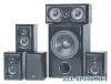 |


Фрагмент инструкции
In AUTO ON, the Subwoofer is in standby mode until it detects an audio signal input, then the Subwoofer turns on automatically. A few minutes after audio input signals cease, the Subwoofer automatically returns to standby mode. POWER INDICATOR LED This LED is unlit when the AC power switch is OFF. It glows red when the Subwoofer is in standby mode ad green when the Subwoofer is on. FUSE 250V 2A This fuse protects against internal and external faults. If the POWER switch is ON and the power indicator LED is unlit, unplug the power cord from the AC outlet and check the fuse by unscrewing the center piece from the holder. IMPORTANT If the fuse is blown, replace it only with a fuse of the same type and current rating. L, R SPEAKER-IN TERMINALS - See Connection Option 1 These terminals are for making connections using speaker wire. If you use this option, do not use Option 2. LINE IN - See Connection Option 2 This jack is for connection using an audio cable. If you use this option, do not use Option 1. LOW PASS FREQUENCY CONTROL Adjusts the upper frequency limit for audio signals going to the Subwoofer amplifier. This control helps you adjust the system tonal balance. LEVEL CONTROL Balances the loudness of the Subwoofer relative to the Front speakers and compensates for room effects on the Subwoofer’s output. PHASE SWITCH The Phase Switch controls the phase of the Subwoofer’s output relative to the front speakers. Listen carefully to the sound quality while playing a CD with low bass. Select the position of the switch that produces the fullest deep bass without boominess. You may need to readjust the Level and Low Pass Frequency controls after setting the Phase Switch. CONNECTING YOU SUBWOOFER IMPORTANT: When you make connections. make sure that the power switches of all components, including the Subwoofer, are OFF. L R + – SPEAKER LEVEL IN LINE PHASE 180° LOW PASS LEVEL MIN MAX50HZ 0° 150HZ PREQUENCY MODEL NO.: ARS108PSB SERIAL NO.: CAUTION: ATTENTION: C TO REDUCE THE RISK OF FIRE REPLCE WITH ONLY THE SAME TYPE AND RATING OF FUSE UTILSER UN FUSIBLE DE RECHANGE MEME TYPE. CONFORMS TO ANSI/UL STD.650D CERTIFIED TO CAN/CSA STD.E65 DOUBLE INSULATION - when servicing use only identiacl replacement parts WARNING: SHOCK HAZARD-DO NOT OPEN AVIS: RISQUE DE CHOC ELETRIQUE-NE PAS OUVRIR 2000772 AUTO FUSE TYPE T2AL 250VCAUTION !RISK OF ELECTRIC SHOCK DO NOT OPEN US 60HZ 200V OFF ON 115V POWER AUDIO CABLES If you are connecting the Subwoofer into a system made up of separate components (preamp & power amps), you will need audio cables long enough to reach the Subwoofer from the preamplifier and the power amplifier. SPEAKER WIRE Typical speaker wire has a pair of separate conductors with insulating jackets that are molded together. We recommend that you use 16-gauge speaker wire for hooking your Receiver to your Front speakers. To make connections to the Subwoofer in parallel with the Front speakers easier, the speaker wire connecting the Receiver to the Subwoofer can be smaller (higher gauge number), since the Subwoofer does not draw large amounts of power through these wires. POLARITY All speakers in a system must be connected with the same polarity. Speaker wire is marked for polarity so that you can identify which wire in the pair is which. Polarity is shown by a color strip on the insulation, by ridges molded into the insulation, or by the colors of the wires - one copper and one silver. Strip the insulation from speaker wire ends to reveal the bare conductors before connecting to Receiver, Subwoofer or Speaker terminals. IMPORTANT Always connect the red + terminal on the Receiver to the red + terminal on the Subwoofer, and the black - terminal on the Receiver to the black - terminal on the Subwoofer. The same is true for hooking the Receiver outputs to the Front speakers: red + to red +, and black- to black-. IMPORTANT USE OPTION 1 OR OPTION 2, NOT BOTH. OPTION 1 – CONNECTION WITH SPEAKER WIRE RECEIVER FRONT LEFT FRONT RIGHT SPEAKER SPEAKER SUBWOOFER Connect speaker wires from the Receiver’s front left and right speaker outputs to the subwoofer’s left and right Speaker In terminals, as well as the left and right front speakers OPTION 2 – CONNECTION WITH AUDIO CABLE RECEIVER L R SPK OUT SPEAKER LEVEL + – + – + – + – LFE or SUBWOOFER LINE IN SUBWOOFER SPEAKERS Connect an audio cable from the Subwoofer Out or LFE Out on the back of your Receiver to the Line In jack on the back of the subwoofer. OPCION DE CONEXION 2 – CONEXION CON CABLE DE AUDIO RECEPTOR SALIDA ALTAVOZ L R + – ++ –– + – LFE o SUBWOOFER ENTRADA DE LINEA SUBWOOFER ALTAVOCES Conectar un cable de audio de la salida ‘Subwoofer Out’ o ‘LFE Out’ en la parte trasera del aparato receptor al conector ‘Line In’ ubicado en la parte trasera del subwoofer AJUSTE Y UTILIZACION DEL SUB-ALTAVOZ PARA GRAVES (SUBWOOFER) CONFIGURACION INICIAL DE LOS CONTROLES DEL SUBWOOFER • Colocar el control de FRECUENCIA DE PASO BAJO en posicion central. • Colocar el control de NIVEL compl...