


Оценок - 4, средний балл: 4
(

 )
)
|
Фото и характеристики Pioneer DEH-2920MP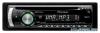 |


К этому устройству также есть другие инструкции:
Автомагнитолы - DEH-2920MP (807.9 kb)
Автомагнитолы - DEH-2920MP (1.07 mb)
Фрагмент инструкции
In this case, be sure to connect 2* to 5* and 4* to 3*. 2. This Product 1. Rear output 3. Antenna jack 4. Fuse (10 A) 7. Connect leads of the same color to each other. 8. Cap (1*) Do not remove cap if this v terminal is not in use. 9. Yellow (3*) Back-up (or accessory) 11. Red (5*) Accessory (or back-up) 10. Yellow (2*) Connect to the constant 12 V supply terminal. 12. Red (4*) Connect to terminal controlled by ignition switch (12 V DC). ¿¿J 13. Black (chassis ground) Connect to a clean, paint-free metal location. 14. ISO connector Note: In some vehicles, the ISO connector may be divided into two. In this case, be sure to connect to both connectors. 27. Yellow/black If you use an equipment with Mute function, wire this lead to the Audio Mute lead on that equipment. If not, keep the Audio Mute lead free of any connections. 16. Connect with RCA cables (sold separately) 17. Power amp (sold separately) 5. Wired remote input Hard-wired remote control adaptor can be connected (sold separately). 18. Blue/white Connect to system control terminal of the power amp (max. 300 mA 12 V DC). 20. Blue/white (7*) Connect to Auto-antenna relay control terminal (max. 300 mA 12 V DC). 21. Blue/white (6*) 19. System remote control 22. The pin position of the ISO connector will differ depends on the type of vehicle. Connect 6* and 7* when Pin 5 is an antenna control type. In another type of vehicle, never connect 6* and 7*. 23. Left 24. Right 25. Rear Speaker © 1 © © © <] 25- Rear Speaker 26. Perform these connections when using the optional amplifier. 15. Speaker leads White: Front left 0 White/black: Front left © Gray: Front right 0 Gray/black: Front right 0 Green: Rear left 0 Green/black: Rear left © Violet: Rear right 0 Violet/black: Rear right © Connecting the Units Note: • When this unit is installed in a vehicle without ACC (accessory) position on the ignition switch, red cable must be wired to the terminal that can detect the operation of the ignition key. Otherwise, battery drain may result. ACC position No ACC position • Use this unit in other than the following conditions could result in fire or malfunction. — Vehicles with a 12-volt battery and negative grounding. — Speakers with 50 W (output value) and 4 ohm to 8 ohm (impedance value). • To prevent short-circuit, overheating or malfunction, be sure to follow the directions below. — Disconnect the negative terminal of the battery before installation. — Secure the wiring with cable clamps or adhesive tape. To protect the wiring, wrap adhesive tape around them where they lie against metal parts. — Place all cables away from moving parts, such as gear shift and seat rails. — Place all cables away from hot places, such as near the heater outlet. — Do not pass the yellow cable through a hole into the engine compartment to connect to a battery. — Cover any disconnected cable connectors with insulating tape. — Do not shorten any cables. — Never cut the ...
Эта инструкция также подходит к моделям:Автомагнитолы - DEH-2900MP (331.75 kb)
Автомагнитолы - DEH-2900MPB (331.75 kb)
Автомагнитолы - DEH-3900MP (331.75 kb)