


Оценок - 0, средний балл: 4
(

 )
)
|
Фото и характеристики LG TCC-9510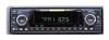 |


Фрагмент инструкции
To avoid electrical shock; do not open the cabinet. Refer servicing to qualified personnel.Shock hazard-do not open. CAUTION Use of controls or adjustments or performance of procedures other than those specified herein may result in hazardous radiation exposure. CAUTION-INVISIBLE LASER RADIATION WHEN OPEN AND INTERLOCKS DFEATED, AVOID EXPOSURE TO BEAM. The lightning flash with arrowhead within an equilateral triangle is intended to alert the user to the presence of uninsulated “dangerous voltage” within the product’s enclosure of sufficient magnitude to constitute a risk to persons. The exclamation point within an equilateral triangle is intended to alert the user to the presence of important operating and maintenance (servicing) instructions in the literature accompanying the appliance. WARNING : To reduce the risk of fire or electric shock, do not expose this appliance to rain or moisture. CAUTION : To prevent electric shock, match wide blade of plug to wide slot, fully insert. 2 10A10A WIRING CONNECTIONS Precaution on making connections Before connecting, make sure that ignition switch is set toOFF, and remove the terminal of the battery to avoid shortcircuits. NoteMake correct connections as illustrated in the connectiondiagram. cord of each speaker in common. 1. VIOLET 2. VIOLET / BLACK STRIPE 3. GRAY 4. GRAY / BLACK STRIPE 5. WHITE 6. WHITE / BLACK STRIPE 7. GREEN 8. GREEN / BLACK STRIPE Never use the 3 WIRING CONNECTIONS From antenna From power amplifier’s input jack( 2channel or 4 channel : optional ) To the wiring of vehicle colors of leads BLACK(Ground lead to be connected to vehicle(metal) body) PINK(Dimmer lead to be connected to Dimmer switch of vehicle) RED(ACC lead to be connected to the terminal from which the power is supplied when the ignition swich YELLOW(Battery lead to be connected to the back up terminal from which power is always supplied) BLUE(To relay box for full automatic power antenna or power amplifier control lead. Power antenna the terminal of the control relay switch for vehicles equipped with a power antenna. This lead is or semiautomatic antennas) Connect the CD changer(optional) Your car receiver works as control unil for a CD changer which you can buy. If not yet done, The suitable cord shown on the scheme will be provided together with the CD changer. 2 - Speaker Connections 4 - Speaker Connections LOUD SPEAKER 1. +Right Rear : VIOLET 5. +Left Front : WHITE 2. - Right Rear : VIOLET/BLACK 6. - Left Front : WHITE/BLACK 3. +Right Front : GRAY 7. +Left Rear : GREEN 4. - Right Front : GRAY/BLACK 8. - Left Rear : GREEN/BLACK 4 HOW TO INSTALL & REMOVE THE APPARATUS 5 NOTE ! Use only the supplied mounting hardware for safe and secure installation. Please consult your nearest dealer if you get any problems with installation. Press the open knob to open up the front panel and detach it by pulling it towards you. Insert the enclosed handles into the slits of the unit, as illustrated, while pressing the handle lightly, then pull the unit out of the holder. HOLDER Insert the holder into the car radio slot. Fasten the holder by pulling and bending the tabs which are located around the holder as illustrated. FRONT PANEL Detaching the front panel 1. Press the open knob to open up the panel. 2. Holding the middle upper side of the panel, pull it straight out towards the arrow direction.(See the figure) 3. The red lamp blinks to tell you that the front panel has detached.(It could be stolen) : Option 4. Keep the front panel in the supplied protection 6 Attaching the front panel 1. Holding the panel at its top and bottom edges. 2. Attach one side of the panel lightly first, then push the other side of the panel into the unit. 3. Do not press the panel hard against the unit. It can be attached by pressing it lightly. And beware not to drop it. Keep in mind: If it works malfunction, take the panel off and put it back again. Do not touch the contact pins on the rear of the front panel, this can cause contact errors. If the contacts are not clean, clean contacts with a cotton swab dipped in alcohol. Do not expose the front panel to direct heat or cold. Be careful not to splash juice or other soft drinks into the car audio. Do not apply too much force. Otherwise, the panel may be damaged. Never take the front panel apart. When front panel is open, beep sound once after 57 seconds, then beep sound twice after 58 seconds and power turns 1 minute. FUNCTION DESCRIPTION, CONTROLS 1. POWER ON/ OFF(PWR) 2. VOLUME UP/ DOWN 3. BAND 4. AUDIO SELECTOR 5. EQ 6. MODE 7. DIR/MUTE 8. LCD 9. INTRO SCAN(INT) 10. REPEAT(RPT) 11. PRESET STATION 12. SUPER-BASS/LOC 7 13. AUT(AUTO TRAVEL PRESET) 14. TUNE(AUTO/ MANUAL) 15. TUNING & TRACK UP/ DOWN (TUN / ) 16. SCAN 17. DISPLAY (DSP) 18. OPEN BUTTON RADIO 1. POWER ON/OFF (PWR ) To switch the audio system on/off, press power button lightly. Simultaneously, the system memorizes all information about its current setting, and restores the information when you turn the syst...