


Оценок - 2, средний балл: 3
(

 )
)
|
Фото и характеристики Vision Fitness X6600HRT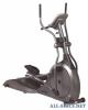 |


Фрагмент инструкции
Be sure to read your Owner’s Guide before using your new Elliptical Trainer. If any parts, hardware or tools are missing, please call 1.800.335.4348, Extension 12 NOTE: It is recommended that you apply grease to the threads of each screw as you assemble your Elliptical Trainer to prevent loosening and noise. Also, during each assembly step, ensure that ALL screws are in place and partially threaded in before completely tightening any ONE screw. 1STEP2STEP3STEP4STEP TOOLS & PARTS INCLUDED 5mm T-Handled Wrench 6mm T-Handled Wrench 17mm Socket Wrench Screwdriver 8mm L-Shaped Wrench PARTS BOX Console Mast Cover Water Bottle Heart Rate Chest Strap Link Arm Covers, Qty: 2 Pedal Support Brackets, Qty: 2 Dual Action End Caps, Qty: 2 Color-coded Hardware Bags Owner’s Guide Assembly Guide Warranty Card 10mm L-Shaped Wrench HARDWARE INCLUDED ORANGE BAG M10x70L CapScrew Quantity: 2 M8x20L Screw Quantity: 2 M20x29x1.5T Wavy Washer Quantity: 2 M8x10L SocketHead CapScrew Quantity: 4 M8x80L SocketHead CapScrew Quantity: 1 PINK BAG Sapcers Quantity: 4 M5x12L Screw Quantity: 6 M5x10x1T Washer Quantity: 4 M10x50L Screw Quantity: 2 M10 Nut Quantity: 2 M8x20L CapScrew Quantity: 8 BLUE BAG 1STEP• Place the console mast boot on the end of the console mast. • Connect the wire tie that exits the bottom of the console mast to the wire harness that sits in the bracket at the top of the frame. Pull the wire tie and wire harness up through the console mast while at the same time inserting the console mast into the frame bracket. • Secure the console mast to the frame with two capscrews (M10 x 70L). Tighten with the 8mm L-shaped wrench. • Stabilize the console mast by inserting the socket head screw (M8x80L) to the front of the bracket. Tighten with the 10mm L-shaped wrench. • Slide the console mast boot down the console mast and snap it in place so it integrates with the side covers. ORANGE BAG • Place the console mast boot on the end of the console mast. • Connect the wire tie that exits the bottom of the console mast to the wire harness that sits in the bracket at the top of the frame. Pull the wire tie and wire harness up through the console mast while at the same time inserting the console mast into the frame bracket. • Secure the console mast to the frame with two capscrews (M10 x 70L). Tighten with the 8mm L-shaped wrench. • Stabilize the console mast by inserting the socket head screw (M8x80L) to the front of the bracket. Tighten with the 10mm L-shaped wrench. • Slide the console mast boot down the console mast and snap it in place so it integrates with the side covers. ORANGE BAG Console Mast 1STEPConsole Mast Boot Bracket 5 2STEP• Place a wavy washer (M20) on the axle located under the foot plate of the right lower link arm. • Slide the axle of the lower link arm into the bracket located on the top of the right pedal arm. Secure the lower link arm to the pedal arm by attaching the pedal support bracket and screw (M8x20L) to the end of the axle. Secure the outside holes in the bracket to the footplate with two sockethead capscrews (M8x10L). Tighten screws with the 5mm T-handled wrench. • Repeat the same steps on the left side. BLUE BAG 2STEPLower Link Arm Pedal Arm • Place a wavy washer (M20) on the axle located under the foot plate of the right lower link arm. • Slide the axle of the lower link arm into the bracket located on the top of the right pedal arm. Secure the lower link arm to the pedal arm by attaching the pedal support bracket and screw (M8x20L) to the end of the axle. Secure the outside holes in the bracket to the footplate with two sockethead capscrews (M8x10L). Tighten screws with the 5mm T-handled wrench. • Repeat the same steps on the left side. BLUE BAG 2STEPLower Link Arm Pedal Arm 6 7 STEP 3 • Connect the right dual-action arm to the right console mast rotation housing, being sure to line up the holes. Secure the dual-action arm in place with four screws (M8x20L) and tighten with the 6mm T-handled wrench. Snap the dual-action end cap into place. • Make sure the spacers are inserted into the outside holes of the ball and socket joint of the lower link arm. Connect the right lower link arm to the right dual-action arm by lining up the holes on the end of each arm. Slide the screw (M10x50L) through the hole. Place a nut (M10) on the screw and tighten using the 17mm socket wrench and 6mm T-handled wrench. • Position the link arm cover over the joint of the lower link arm and dual-action arm. With a screw (M5x12L) and the screwdriver, connect the two halves of the cover through the hole located in the front of the cover. Attach the cover to each side of the lower link arm with the two washers (M5) and two screws (M5x12L). • Repeat these same steps on the left side. PINK BAG STEP 3 Rotation Housing Link Arm Cover Dual-Action End Cap Dual-Action Arm Fig. A Fig. A STEP 4 • Remove the four screws from the back of the console. • Make sure the 9-Volt battery is plugged in and in place in the back of the console. • Plug...