


Оценок - 4, средний балл: 3.8
(

 )
)
|
Фото и характеристики Spirit XU875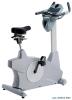 |


Фрагмент инструкции
3/8.. x 1-3/4.. Hex Head Screw (4 pcs) #77.3/8" x 19 x 1.5T Flat Washer (4 pcs) Step 3 #89. 3/8" x 7T Nyloc Nut (4 pcs) #99. M5 x 12m/m Phillips Head Screw (4pcs) #98. M6 x 15m/m Phillips Head Screw (4pcs) Step 4 #70. 5/16.. x 1-3/4.. Hex Head Screw (1 pc) #105. 4 x 16m/m Self Tapping Screw (4 pcs) #76. 5/16" x 19 x 1.5T Flat Washer (1 pc) #91. 5/16" x 6T Nylon Nut (1 pc) Tools #114. Phillips Screw Driver (1 pc) #115. M5 Allen Wrench (1pc) #112. 12/14m/m Wrench (1 pc) #113. 13/15m/m Wrench (1 pc) #130. 13/14m/m Wrench (1 pc) 7 XU875 & XR895 8 XU875 & XR895 .. UNPACKING THE UNIT 1. Cut the straps then lift the carton off. 2. Carefully remove all parts from carton and inspect for any damage or missing parts. If damaged parts are found, or parts are missing, contact your dealer immediately. 3. Locate the hardware package. The hardware is separated into four steps. Remove the tools first. Remove the hardware for each step as needed to avoid confusion. The numbers in the instructions that are in parenthesis (#) are the item number from the assembly drawing, for reference. STEP 1: REAR STABILIZER & SEAT BACK ASSEMBLY 1. Install the Rear Stabilizer (7) onto the Main Frame with the 4pcs of 3/8.. x 2-1/4.. Hex Head Screws (65) and 4pcs of 3/8.. Flat Washers (84) using the 12/14mm Wrench (112). 2. Install Seat Back Frame (5) onto the Seat Carriage (4) with the 2pcs of 3/8.. x 4.. Hex Head bolts (67), 3/8.. Flat Washers (77) and 3/8.. Nyloc nuts (89) by using the 12/14mm Wrench (112). Tighten the bolts snugly enough so the seat back has no play but does not bind when reclining. Assembly Instructions (XR895) 9 XU875 & XR895 STEP 2: CONSOLE MAST ASSEMBLY 1. Install the Console Mast Cover (31) onto the console mast (2). Make sure the plastic cover is in the correct orientation. 2. Connect the Upper Computer Cable (44) from the console mast to the lower Computer Cable (45) and Speed Sensor Cable (46) from the receiving tube in the main body of the bike. 3. Install the Console Mast (2) into the receiving tube (make sure not to pinch the wire cables (44,45,46). Damage to the electronics could occur) of the Main Frame with the 6pcs of 5/16..x15mm Hex Head Screws (68), 4pcs of 5/16.. x 19 x 1.5T Flat Washers (76) on the sides and 2pcs of 5/16..x20 x 1.5T Curved Washers (83) on the front by using the 12/14mm Wrench (112). 4. Install the Upper Computer Cable (44) into the connector in the back of the Console (19). Install the console onto the mounting plate with the 4pcs of M5x12mm Phillips Head Screws (99) by using the Phillips Head Screw Driver (114). 5. Install the Handle Bar (3) onto the Console Mast (2) with the 2pcs of 5/16.. x 15mm Hex Head Bolts (68), 2pcs of 5/16.. x 20 x 1.5T Flat Washers (83) and 2pcs of 8m/m x1.5T Split Washers (82) by using the 12/14mm Wrench (112). 1 0 XU875 & XR895 STEP 3: SEAT & HANDLE BAR ASSEMBLY 1. Install the Seat Cushion (61) on the Seat Carriage (4) with the 4pcs of M6x15mm Phillips Head Screws (98). 2. Install the Handle Bar (6) onto the Seat Carriage (4) with the 4pcs of 3/8.. x 1-3/4.. Hex Head Bolts (71), 4pcs of 3/8.. x 19x1.5T Flat Washers (77), and 4pcs of 3/8.. x 7T Nyloc Nuts (89) by using the 12/14mm Wrench (112). 3. Then plug the Hand pulse Cables (27~3)(27~4) into the sockets located on the left side rear cover (26), just under the seat. It does not matter which connector plugs into which socket. 4. Install the Front Stabilizer Cover (32) and the Rear Stabilizer Cover (37) on the Main Frame with the 4pcs of M5x12mm Phillips Head Screws (99). 1 1 XU875 & XR895 STEP 4: RELEASE LEVER ASSEMBLY 1. Run the Seat Recline Release Cable (58) under the Seat Back Frame (5). 2. Install the Gas Cylinder (57) into the bracket of the Seat Back Frame (5) with the 1pc of 5/16.. x1-3/4.. Hex Head Bolt (70), 1pc of 5/16.. x 19 x 1.5T Flat Washer (76), 1pc of 5/16..x 6T Nyloc Nut (91) by using the 13/14mm Wrench (130) and 13/15mm Wrench (113). Tighten the bolt until snug, but do not over tighten to the point of binding. 3. Remove the M6 Button Head Socket Screws holding the clamps of the left and right Release Levers (40) by using the Allen Wrench (115). Install the 2 Release Levers (40) onto the Handle Bar (6) just behind the hand pulse sensors. Install them at an angle that allows easy access for use, then install and tighten the socket screws removed earlier. 4. Secure the Seat Recline Release Cable (58) and the Seat Fore/Aft Release Cable (59) on the Handle Bar (6) by using the 4pcs of Velcro Tape. Wrap the tape around the handlebars in places that will be under the beverage holders, when they are installed, so they are out of sight. 5. Install the Beverage Holders (38 L, 39 R) on the Handle Bar (6) with the 4pcs of 4x16m/m Self Tapping Screws (105) by using the Phillips Head Screw Driver (114). 6. Install the Pedals (116 L, 117 R) in the Cranks by using the 13/15mm Wrench (113). Remember that the left pedal has a reverse thread and will be screwed into the crank in the opposite rotation from n...
Эта инструкция также подходит к моделям:Тренажеры - XR895 (854.48 kb)