


Оценок - 2, средний балл: 3
(

 )
)
|
Фото и характеристики Life Fitness 95Si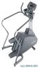 |


Фрагмент инструкции
Detach and feed the CONSOLE WIRE HARNESS (C) through the MONOCOLUMN and out through the DISPLAY CONSOLE MOUNTING BRACKET (D) ACCESS HOLE. Pivot the MONOCOLUMN upright and position the locating slot at the bottom of the MONOCOLUMN onto the preinstalled LOCATING BOLT (E) on the MONOCOLUMN MOUNTING BRACKET. Align the mounting holes of the MONOCOLUMN and MONOCOLUMN MOUNTING BRACKET and secure them together using two MOUNTING BOLTS (#1) and LOCKNUTS (#2). Leave the BOLTS and NUTS loose at this time. Lower the MONOCOLUMN SHROUD until it rests on the MAIN SHROUDS. CAUTION: BE CAREFUL NOT TO PINCH THE WIRE HARNESS (C). MISE EN GARDE : VEILLEZ A NE PAS PINCER LE FAISCEAU (C). 3. Align and insert the HANDLEBAR ASSEMBLY (#15) into THE HANDLEBAR BRACKET TUBE (F) as shown until the mounting holes in the HANDLEBAR ASSEMBLY align with those of the HANDLEBAR BRACKET TUBE. 14 2PL 2P 15 F 10 13 2PR 2P 6 J 19 8 15 F 8 16 4. Locate the TELEMETRY CABLE (#17). Feed the 3-PIN CONNECTOR (3P) end of the cable through the front of the HANDLEBAR ASSEMBLY (#15). The cable must be routed down the HANDLEBAR BRACKET TUBE (F) and back up the top of the MONOCOLUMN (#10). Feed the 3-PIN CONNECTOR through the DISPLAY CONSOLE MOUNTING BRACKET (D) ACCESS HOLE. Locate the HEART RATE CABLE (#18). In similar fashion, feed the 4-PIN CONNECTOR (4P) end of the cable through the front of the HANDLEBAR ASSEMBLY (#15). The cable must be routed down the HANDLEBAR BRACKET TUBE (F) and back up the top of the MONOCOLUMN (#10). Feed the 4-PIN CONNECTOR through the DISPLAY CONSOLE MOUNTING BRACKET (D) ACCESS HOLE. Pull the LEFT HEART RATE SENSOR CABLE (2PL) (Labeled LEFT) through the LEFT LARGE HOLE (H) of THE HANDLEBAR BRACKET TUBE. Pull the RIGHT HEART RATE SENSOR CABLE (2PR) (Labeled RIGHT) through the RIGHT LARGE HOLE of THE HANDLEBAR BRACKET TUBE. 5. Locate the USER LEFT BULLHORN (#13) with a Lifepulse sensor. Connect the 2-PIN CONNECTOR (2P) leading from the USER LEFT BULLHORN to the 2-PIN CONNECTOR (2PL) now leading from the HANDLEBAR BRACKET TUBE (F). Carefully feed any excess HEART RATE CABLE (2PL) into the HANDLEBAR BRACKET TUBE and secure the USER LEFT BULLHORN to the HANDLEBAR BRACKET TUBE using three MOUNTING SCREWS (#6). Tighten the SCREWS securely. Repeat the procedure for the USER RIGHT BULLHORN (#14) with a Lifepulse sensor. 6. Locate the POLAR RECEIVER ASSEMBLY (#16). Plug the POLAR RECEIVER ASSEMBLY into the POLAR RECEIVER JACK (J). Place the POLAR RECEIVER in a vertical position, POLAR RECEIVER JACK facing downward, at the front of the HANDLEBAR BRACKET TUBE (F). Position the POLAR COVER (#19) over the center of the HANDLEBAR ASSEMBLY (#15) at the HANDLEBAR BRACKET TUBE. Making sure the POLAR COVER is oriented properly, slide the POLAR COVER over the HANDLEBAR ASSEMBLY covering the POLAR RECEIVER ASSEMBLY and the end of the HANDLEBAR BRACKET TUBE. The POLAR COVER should fully nest over the HANDLEBAR ASSEMBLY. Secure the POLAR COVER using two MOUNTING SCREWS (#8). CAUTION: DO NOT OVER-TIGHTEN THE PHILLIPS CAP HEAD SCREWS (#8). MISE EN GARDE : NE SERREZ PAS EXCESSIVEMENT LES VIS CRUCIFORMES A TETE CYLINDRIQUE (N. 8). 10 3P 15 F D 17 15 4 12 K 3 5 10 D 5 11 9 L 20 K 7. Locate one of the VERTICAL HANDRAILS (#12). Carefully insert the top of the VERTICAL HANDRAIL into the user right end of the HANDLEBAR ASSEMBLY (#15). Align the mounting holes. Secure the VERTICAL HANDRAIL to the HANDLEBAR ASSEMBLY using two MOUNTING SCREWS (#4). Position the bottom of the VERTICAL HANDRAIL over the mounting hole in the top of the right FRAME LEG (K). Using one HEX HEAD BOLT (#3), mount the VERTICAL HANDRAIL to the right FRAME LEG as shown. Tighten the BOLT securely. Repeat the procedure for the remaining VERTICAL HANDRAIL (#12) on the left side of the HANDLEBAR ASSEMBLY and FRAME. 8. Lift the MONOCOLUMN SHROUD (A) and tighten the MONOCOLUMN BOLTS (#1) securely. CAUTION: DO NOT OVER-TIGHTEN THE BOLTS (#1). MISE EN GARDE : NE SERREZ PAS TROP LES BOULONS (N. 1.) 9. Using four MOUNTING SCREWS (#5), attach the ACCESSORY TRAY (#11) to the DISPLAY CONSOLE (#9) as shown. CAUTION: DO NOT OVER-TIGHTEN THE SCREWS (#5). MISE EN GARDE : NE SERREZ PAS TROP LES VIS (N. 5). 10. Attach all CABLES (L) leading from the DISPLAY CONSOLE MOUNTING BRACKET (D) ACCESS HOLE to the back of the DISPLAY CONSOLE (#9). 11. Feed any excess cable into the MONOCOLUMN (#10). Using four MOUNTING SCREWS (#5), secure the DISPLAY CONSOLE (#9) to the DISPLAY CONSOLE MOUNTING BRACKET (D). CAUTION: DO NOT OVER-TIGHTEN THE PHILLIPS HEAD PAN SCREWS (#5). CAUTION: BE CAREFUL NOT TO PINCH THE WIRE HARNESS (E) WHEN ASSEMBLING THE CONSOLE ASSEMBLY (#9) TO THE DISPLAY CONSOLE MOUNTING BRACKET (D). MISE EN GARDE : NE SERREZ PAS TROP LES VIS CRUCIFORMES A TETE CYLINDRIQUE (N. 5). MISE EN GARDE : VEILLEZ A NE PAS PINCER LE FAISCEAU DE CABLES (E) LORS DU MONTAGE DE LA CONSOLE (N. 9) SUR SON SUPPORT (D). 12. Secure the MONOCOLUMN SHROUD (#21) to the MAIN SHROUD using four MOUNTING SCREWS (#7). CAUTION: DO NOT OV...