


Оценок - 4, средний балл: 3.5
(


 )
)
|
Фото и характеристики Antec SOLO II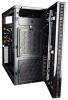 |


Фрагмент инструкции
-Check your motherboard’s CPU socket to ensure its compatibility with the KUHLER H2O. The KUHLER H2O 620 / 920 is compatible with the following CPU sockets: Intel® LGA 1155 / 1156 / 1366 / 2011 AMD® AM2 / AM3 / AM2+ / AM3+ - Be sure to install the KUHLER H2O with the end of the tubes positioned at the bottom of the radiator. 1. Remove the TrueQuiet™ fan mounting pins by pulling slowly on the head of the mounting pin while pushing the tail of the pin through the rear of the case. This ensures that the mounting pins stay intact. Apply a firm, consistent force, but do not yank the pin through. 2. The TrueQuiet™ fan has two small black clips attached to the fan’s two-speed switch. With your thumb and forefinger, spread the clips while pushing from the rear of the case to remove the switch. 3. Preparing the KUHLER H2O backplate is specific to your CPU socket. Please refer to the KUHLER H2O installation guide, available at (KUHLER H2O 620) or (KUHLER H2O 920) for more information. 4. Prepare the retention ring according to the CPU socket you’re using. 5. Complete installation according to the KUHLER H2O instructions. POWER SUPPLY INSTALLATION We recommend removing the PSU support beam to facilitate installation. The power supply support beam has two screws on both sides: two attached to the 5.25” drive cage and two at the rear. 1. Locate and remove the first screw on the drive cage. 2. Remove the second screw with your other hand supporting the beam so the beam won’t drop. 3. Repeat steps 1 and 2 for the support beam screws at the rear of the case. . 4. Place the SOLO II on its side. Position the PSU into the mount and secure it with the PSU screws provided. If your PSU has a fan on its top side, make sure it aligns with the SOLO II’s top intake vent. 5. Re-attach the PSU support beam. CABLE MANAGEMENT There is a cable management area between the motherboard and right side panel as well as cable hooks located on the side of the 3.5” drive cage. You can tuck excess cables in this area or route them to the drive bays. Choose the cables you would like to pass through the holes behind the motherboard tray. Pull them through the hole toward the right side of the case. For cables which will be routed directly to front drives or other internal accessories, cable hooks are located along the drive cage. Bundle front drives’ or other internal accessories’ cables together and secure them using the hooks. EXTERNAL 5.25” DEVICE INSTALLATION There are two externally accessible 5.25” drive bays. Before you begin, remove the 5.25” drive bay covers on the rear of the front bezel. To install a 5.25” drive: 1. Locate and remove two 5.25” rails from the bottom of the case. 2. Attach the drive rails to your 5.25” device. These rails have three depth settings that accommodate the depth of your 5.25” drive. 3. Make sure to properly align your drive rails with your 5.25” drive. We recommend attaching one rail with one of the 5.25” drive screws and closing the bezel as a trial. Use the four 5.25” drive screws to secure your drive. 4. Slide the 5.25” drive into the appropriate drive bay. You will know the drive is secure when you hear a “click.” 5. Mount any other 5.25” devices accordingly. INTERNAL 3.5” AND 2.5” INSTALLATION (TRAY MOUNTS AND SUSPENSION MOUNTING SYSTEM) The following text outlines the preparatory stages for installing 3.5” / 2.5” drives using drives trays and the suspension mounting system. 1. If you have reattached it, remove the left side panel. Loosen the side panel screws and swing the panel outward, pulling it back towards you; this will completely remove it. 2. Remove the front bezel by locating the bezel tabs and pulling them to release the bezel .The bezel will swing outward like a door. Lift the bezel upwards to remove it from its hinges. 3. Open the drive cage by loosening the top thumbscrew. For Tray Mount Installation: The SOLO II comes preinstalled with silicone grommets positioned for 3.5” drive installation. You may remove the grommets and position them as so to accommodate a 2.5” drive. 3.5” position 2.5” position 4. Position your drive on top of the grommets with the SATA connectors facing away from the tray rails. Turn the tray + drive upside-down, and secure the drive using the appropriate tray-mount screws. Do not over-tighten the screws, as this will cause the grommets to lose their sound- dampening function. 3.5” drive 2.5” drive 3.5” drive 2.5” drive 5. Insert the 3.5” / 2.5” drive into the drive cage by pinching the ends of the drive tray and sliding the tray along the rails until the tray locks firmly into position. 3.5” drive 2.5” drive 6. Mount any other 3.5” / 2.5” devices accordingly. For Suspension Mounting Installation: The SOLO II accommodates two 3.5” drives using the suspension mounting system. Each hard drive needs two suspenders (front and rear) to mount. Note: Please ...