


Оценок - 3, средний балл: 4
(

 )
)
|
Фото и характеристики Smeg KSET66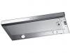 |


Фрагмент инструкции
MAINTENANCE • Switch off or unplug the appliance from the mains supply before carrying out any maintenance work. • Clean and/or replace the Filters after the specified time period. • Clean the hood using a damp cloth and a neutral liquid detergent. 650mm.min. GB 10 GB 11 0.152 280 L 260 o150 Hood Type 60 90 L 598 898 1 12a 20 CHARACTERISTICS Dimensions Components Ref. Q.ty Product Components 1 1 Hood Body, complete with: Controls, Light, Blower, Filters 20 1 Closing element Ref. Q.ty Installation Components 12a 4 Screws 4,2 x 44,4 Q.ty Documentation 1 Instruction Manual INSTALLATION Drilling the Support surface and Fitting the Hood SCREW FITTING • The hood support surface must be 220 mm above the bottom surface of the wall units. • Drill the support with a o 4,5 mm drill bit, using the drilling template provided. • Cut a hole o 150 mm in size on the support surface, using the drilling template provided. • Fix using the 4 screws 12a (4,2 x 44,4) provided. 220 SNAP-ON FITTING • The hood can be installed either directly on the bottom surface of the wall units (min. 650 mm above the hob) using snap-on side supports. • Cut a fitted opening in the bottom surface of the wall unit, as shown. • Insert the hood until the side supports snap into place. • Lock in position by tightening the screws Vf from underneath the hood. Hood Type 60 90 L 598 898 15264L1Vf GB 12 GB 13 CLOSING ELEMENT • The space between the edge of the hood and the rear wall can be closed by applying the element 20 provided, using the screws supplied for this purpose. Connections DUCTED VERSION AIR EXHAUST SYSTEM When installing the ducted version, connect the hood to the chimney using either a flexible or rigid pipe o 150 mm, the choice of which is left to the installer. • Fix the pipe in position using sufficient pipe clamps (not supplied). • Remove any activated charcoal filters. RECIRCULATION VERSION AIR OUTLET • Cut a hole o 150 mm in the wall unit over the hood. • Connect the hood body outlet to the top part of the wall unit using a rigid or flexible pipe o 150 mm, to be selected by the installer. • Fix the pipe in position using sufficient pipe clamps (not supplied). • Ensure that the activated charcoal filters have been inserted. ELECTRICAL CONNECTION • Connect the hood to the mains through a two-pole switch having a contact gap of at least 3 mm. • When opening the sliding carriage for the first time after installing the hood, pull it out briskly until it clicks. 20 9 112550 o150 USE Control panel LV01 L Light Switches the lighting system on and off. M Motor Switches the extractor motor on and off. V Speed Sets the operating speed of the extractor: 1. Low speed, used for a continuous and silent air change in the presence of light cooking vapour. 2. Medium speed, suitable for most operating conditions given the optimum treated air flow/noise level ratio. 3. Maximum speed, used for eliminating the highest cooking vapour emission, including long periods GB 14 MAINTENANCE Grease filters • The filters must be cleaned every 2 months of operation, or more frequently for particularly heavy usage. • Remove the filters, one at a time, after disconnecting the relative fastening elements. • Wash the filters, taking care not to bend them. Allow them to dry before refitting. • When refitting the filters, make sure that the handle is visible on the outside. Odour filters (Recirculation version) CLEANING METAL GREASE FILTERS REPLACING ACTIVATED CHARCOAL FILTERS • These filters are not washable and cannot be regenerated, and must be replaced approximately every four months of operation, or more frequently with heavy usage. • Remove the grease filters. • Remove the saturated activated charcoal filters, as shown (A). • Fit new filters (B), as shown. • Replace the grease filters. Lighting AB LIGHT REPLACEMENT • 20 W halogen light. • Remove the 2 Screws fixing the Lighting support, and pull it out of from the Hood. • Extract the Lamp from the Support. • Replace with another of the same type, making sure that the two pins are properly inserted in the lamp holder socket holes. • Replace the Support, fixing it in place with the two Screws removed as above. 15 GB Chere Madame, Cher Monsieur, Si vous suivez attentivement les recommandations contenues dans ce mode d’emploi, votre hotte restera toujours efficace, et fournira constamment les memes performances. SOMMAIRE CONSEILS ET SUGGESTIONS 17 CARACTERISTIQUES 18 INSTALLATION 19 UTILISATION 21 ENTRETIEN 22 FR 16 CONSEILS ET SUGGESTIONS INSTALLATION • Le fabricant decline toute responsabilite en cas de dommage du a une installation non correcte ou non conforme aux regles de l’art. • La distance minimale de securite entre le plan de cuisson et la hotte doit etre de 650 mm au moins. • Verifier que la tension du secteur correspond a la valeur qui figure sur la plaquette apposee a l’interieur de la hotte. • Pour les Appareils appartenant a la Iere Classe, veiller a ce que la mise a la terre de l’installation electrique d...
Эта инструкция также подходит к моделям:Кухонная посуда - KSET96 (2.63 mb)